Summary
Since the introduction of emissions compliant diesel engines into the off highway market (Construction and Agricultural sectors in particular) there has been an increase in the number of incidences of premature diesel injector failure.
This note is intended to help the end user and others with an interest in the problem to understand why this is happening, what tests can be carried out to confirm a problem and how to take measures to avoid the problem in the future. The note is not aimed at any particular manufacturer but highlights a generic and known problem seen in the field.
Introduction
In order to understand the failure mode of the modern fuel injector it is necessary to understand a little about the method of operation as it differs in one key aspect from the older fuel injectors used on earlier engine types.
From the point of view of the injector failure how the system generates injection pressure is not that critical. The methods used on low emissions engines generally fall into the following categories:
1) Unit injector, where the fuel
pump and the injector are contained in the same body with one injector/pump
per cylinder.
2) Common rail, where the fuel is pressurised to injection pressure in a fuel
rail which feeds each injector.
3) Unit pump, where there is one high pressure pump per cylinder linked to a
fuel injector by a short pipe.
All of these types of system have one thing in common: they all control the start and end of injection using a "spill control valve".
There are other systems but these are far less common, those listed above cover the majority of large, industrial type engines found in Agricultural and Construction machinery
The traditional fuel systems used a "pump, line, nozzle" set up where the fuel was pumped to a high pressure by the pump plungers driven by a cam shaft in the fuel pump. Fuel was delivered to each injector by a thick walled steel fuel pipe, with one per cylinder coming from the fuel pump to each individual injector. The start of injection was dictated by the setting of the injector nozzle, fuel being delivered into the cylinder when the pressure in the fuel line rose above the nozzle opening pressure and ending when the pressure dropped below this pressure.
There are several problems with this type of arrangement, particularly with respect to emissions control, namely the limited options for shaping the torque curve of the engine due to the complex nature of the governor required, the limited ability to change the injection timing with speed and load and the problems associated with poor control of end of injection.
The way in which the modern emissions compliant engine over comes these problems is to utilise an electronic engine management system (ECM) to control timing and duration of the fuel injection. The ECM comprises a computer, various temperature, pressure and position sensors around the engine and the necessary electronics to drive system components such as the fuel injectors, waste gate actuator and other control valves.
The way in which the ECM controls the fuel injection is to control the "spill control valve" on the fuel injector.
The Spill Control Valve
In the modern low emissions engine the fuel injection is controlled by the spill control valve. What the spill control valve does is to prevent the rise of fuel pressure in the fuel injector by staying open until closed by an electrical signal from the ECM. Once the pressure in the injector has risen above the nozzle opening pressure fuel is injected into the cylinder. End of injection is controlled when the spill control valve is opened (by removing the electrical signal from the ECM) and injection ends.
Typically fuel pressure in low emissions engines are in the range 1600 to 2200 bar.The spill control valve has to be capable of opening and closing with such pressure present and also of being operated by a relatively low power electrical signal from the ECM. The design of the valve is such that the pressure acting on both sides of the valve are balanced, the additional force required to move the valve from the open to the closed position is provided by an electromagnet which the ECM controls.
An important consideration of the design of the electromagnet is that is has to operate at high speeds and for this to take place it is desirable for the magnetic force applied to the valve is kept to as low a force as possible as the magnetic field takes a finite time to decay before the valve will move.
The valve itself has no seals inside and relies on very accurately machined components with a running clearance in the order of 1.5 to 3 microns (for comparison purposes the average human hair is about 40 microns in diameter!) to prevent fuel leakage.
The problem
It is clear that the spill control valve, with its small operating force and very tight clearances, is going to be very sensitive to dirt in the fuel.
This is not new to diesel fuel systems so why the problems?
Most operators are aware of the need to have good fuel filtration and to avoid water contamination of fuel if they wish their fuel systems to run without failure. There are, however, two other sources of contamination commonly over looked, firstly and of a lesser nature is the contamination drawn into the fuel tanks through fuel tank breathers as the tank is emptied during work (this can also be a source of water contamination due to the formation of condensate) but the other, far less obvious, source is bacterial infection within the main fuel supply tanks at the farm yard or depot.
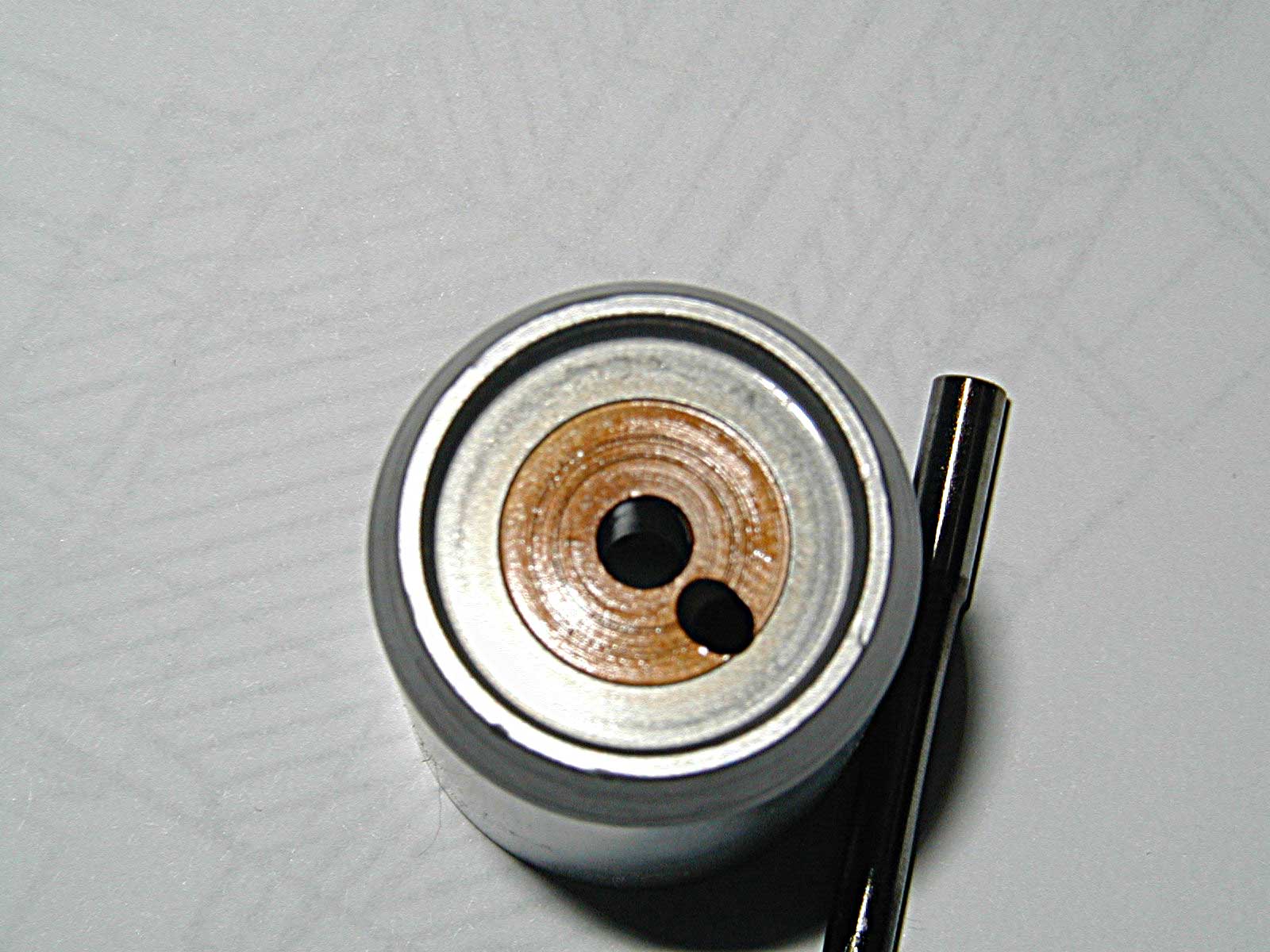
The modern diesel engine uses a fuel filter with a much finer mesh inside than was traditionally used and bacterial infection of the fuel may manifest itself in the form of short filter life. The problem is caused by the residue left behind in the fuel when the bacteria die. This can have the appearance of a brown coloured stain and can be removed from metallic surfaces it has come into contact with buy gently rubbing it with a finger tip. This residue will stick to the filter and clog it fairly quickly but some of the residue will pass through the filter and end up on the surfaces of the fuel system. The photograph below shows an example of this coating on the back end of the fuel injector nozzle. The brown tarnish is only present where the fuel has come into contact with the metal.
More serious is what happens when the bacterial residue is heated. The photograph below shows the needle from the same injector nozzle assembly:
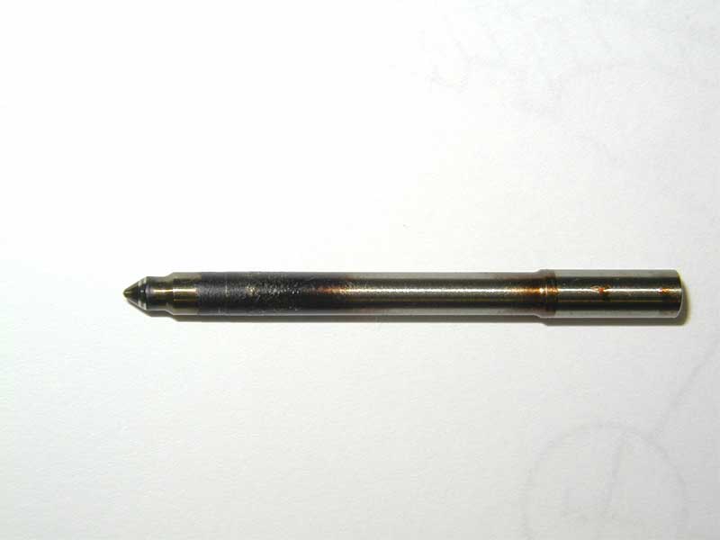
In this case the residue has been carburised (turned to soot). This is not because the needle has been leaking; right up until the failure of the injector the engine was running evenly and the emissions analyser measuring the exhaust gas from the engine showed no signs of a fault of this nature. The engine had been shut down from full power (850 HP) by an alarm trip and the injector was found to be faulty on re-start, some thirty minutes after the original shutdown.
The carburised look comes about because the bacterial residue contains a lot of sugars which are being caramelised by the heat. This does not require a particularly high temperature to take place either. On this injector it was necessary to use a brass drift to punch the spill control valve spool from its body. When the spool was removed it was found to be covered in a dry residue showing partial signs of caramelising.
The spill control valve is surrounded
by the windings of the electromagnet used to operate it. The windings are normally
cooled by the fuel flowing through the spill control valve. In the event of
a fast shutdown of the engine after heavy work or due to an emergency stop the
heat from the engine "soaks" up through the cylinder head and up through
the injector causing the temperature of the spill control valve to rise. The
temperatures seen on an engine shut down in this way can be very high because
the water pump is not moving the water round the engine and "after boiling"
can take place. Because of this the temperature around the spill control valve
may rise high enough to cause the bacterial residue to become caramelised. The
sticky layer of caramel in the very tight clearances of the spill control valve
will exert enough force to prevent the valve from operating and the injector
fails.
What to do about this
The first course of action should be to identify the source of the bacterial infection. Air BP* sell an easy to use microbial test kit that allows the end user to identify the presence of bacterial infection in fuel. Once a source has been identified the user should contact their fuel supplier.
It must be stated here that in all probability the supplier is supplying clean, uninfected fuel and that the problem is arising in the yard tank so be polite when asking for help and advice.
If there is found to be a bacterial infection in the fuel then it will be necessary to either stop using that tank or dose the fuel in the tank with a specific disinfectant. The fuel in the tank will then have to be filtered using a special filtration system to remove the bacterial residues. It may be more appropriate to install a new tank and review the process used to maintain the tank with respect to water drains and tank breathers.
Prevention of failures
There are a few things that can be done to try to prevent injector failures caused by bacterial infection.
1) Shut the engine down in a controlled fashion, idle down as you would for a turbocharger. This will help prevent the engine from heat soaking the injector.
2) If it is necessary to shut down the engine in an emergency try get it restarted as soon as possible and allow it to cool down as above.
3) Use fuel from a known "clean" supply and avoid using fuel cans wherever possible.
4) Check your fuel tank regularly for bacterial infection, just before ordering the next batch of fuel to limit the amount of cleaning required.
5) Look out for signs of bacterial residue during filter changes and use short filter life as a warning of possible problems.
*Air BP can be contacted on +44 (0) 1442 223966 or via e-mail: microbmonitor2@bp.com
© D G Quirk, 2024